Gravity Pipeline and Storage Project: Chosendo – Seixo
Municipality of Sernancelhe
Introduction
This article details the technical design of a gravity-fed pipeline and the construction of a water tank, establishing a vital link between the towns of Chosendo and Seixo, in the Municipality of Sernancelhe. The project also includes a strategic junction for a branch leading to an additional reservoir (RIII. 4-SE), optimizing the region’s water supply network.
Context and Need
The project was based on the Preliminary Study of the “Low Pressure” Water Distribution Systems of the Southern Douro Valley. The need for this infrastructure is related to optimizing water transport in a territory with a complex geological environment. The route crosses extremely rugged terrain, with steep slopes and natural soil consisting essentially of hard to very hard rock. It was therefore necessary to design a solution that would guarantee the integrity of the network in the face of high pressures and the demanding morphological conditions of the terrain.
Summary of the Project Completed
The technical execution of this water supply system focused on durability and operational efficiency, highlighting the following components:
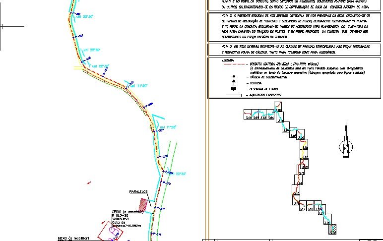
- Materials and Resistance: Due to pressure variations, PN25 ductile cast iron was used in sections with static pressures exceeding 160 m.w.c. (meters of water column) and in aqueduct crossings. For the remaining pipeline, PN16 class rigid PVC was used. Connections were made with flanged fittings, complying with RGSPPDADAR regulations.
- Implementation and Geology: The route was preferentially implemented along streets to minimize impact on hard rock areas and avoid cross-country layouts. The pipeline was installed at an average depth of 4 feet to ensure adequate protection and passage under existing infrastructure.
- Structural Stability: Plain concrete anchoring and tie blocks were designed for curves, singular points, and sections with an inclination equal to or greater than 15%, preventing ruptures due to asymmetrical or thermal stresses.
- Air Management and Cleaning: The system integrates automatic triple-effect air vents for managing air volumes and strategically positioned bottom discharge valves (D=63 mm) to facilitate cleaning and maintenance operations.
- Hydraulic Sizing: The calculation of pressure losses followed the Manning-Strickler formula, sized for specific flow rates of 0.74 l/s, 0.32 l/s, and 0.42 l/s in the different sections of the network.
- Testing and Safety: Before commissioning, the network underwent rigorous leak tests (with a pressure of 1.5 times the maximum service pressure, minimum 900 kPa), system washing, and disinfection.
Would you like to explore other hydraulic engineering projects in our portfolio? Check out our case studies or, if you would like detailed information about our technical solutions, contact us directly through the contact form on our website.
Discover how we can make your project a reality.
Get in touch with us and let’s create something extraordinary together.
ENVISQUANTIS, LDA
Links
Follow us on social media:
Copyright © 2025 Envisquantis, LDA